Data Center Power Generation: A Strategic Guide for 2026
Explore modern data center power generation strategies, from grid interconnection and on-site generation to redundancy sizing and emissions management.
15 min read
Data centers consumed about 415 terawatt-hours of electricity worldwide in 2024, equal to roughly 1.5% of global electricity consumption, according to the International Energy Agency's analysis of energy demand from AI. That demand had grown at about 12% per year over the previous five years, so data center power generation is no longer a narrow facilities concern. It's a strategic question involving grid access, construction schedules, fuel security, redundancy, emissions, and the practical limits of local infrastructure.
The engineering challenge is also easy to misread. A generator can produce power, but it can't solve a substation queue, replace a fuel delivery plan, or automatically satisfy an emissions target. A resilient design connects all of those decisions, from the transmission voltage entering the site to the batteries carrying the load while generators start.
Table of Contents
- Understanding Data Center Power Scale
- Grid Interconnection and High Voltage Distribution
- On-Site Generation Technology Options
- Sizing and Redundancy Architecture
- Fuel Storage and Supply Chain Management
- Emissions Impact and Environmental Trade-offs
- Integration Strategies for Mixed Generation Systems
Understanding Data Center Power Scale
Data centers consumed 415 TWh of electricity in 2024, about 1.5% of global electricity consumption, according to the IEA reports. Demand had grown roughly 12% annually over the preceding five years. For facility managers, those figures establish the scale of the planning problem. A power system designed only for today's load may become a limitation before the electrical plant reaches the end of its useful life.
The more useful question is how that demand is distributed. The United States accounted for 45% of global data center electricity use in 2024, China 25%, and Europe 15%. Concentration creates strong regional pressure, but it does not produce one universal generation plan. A United States site may be constrained by transmission congestion and permitting, while a European facility may face different land, environmental, and generation requirements.
Load size changes the engineering problem
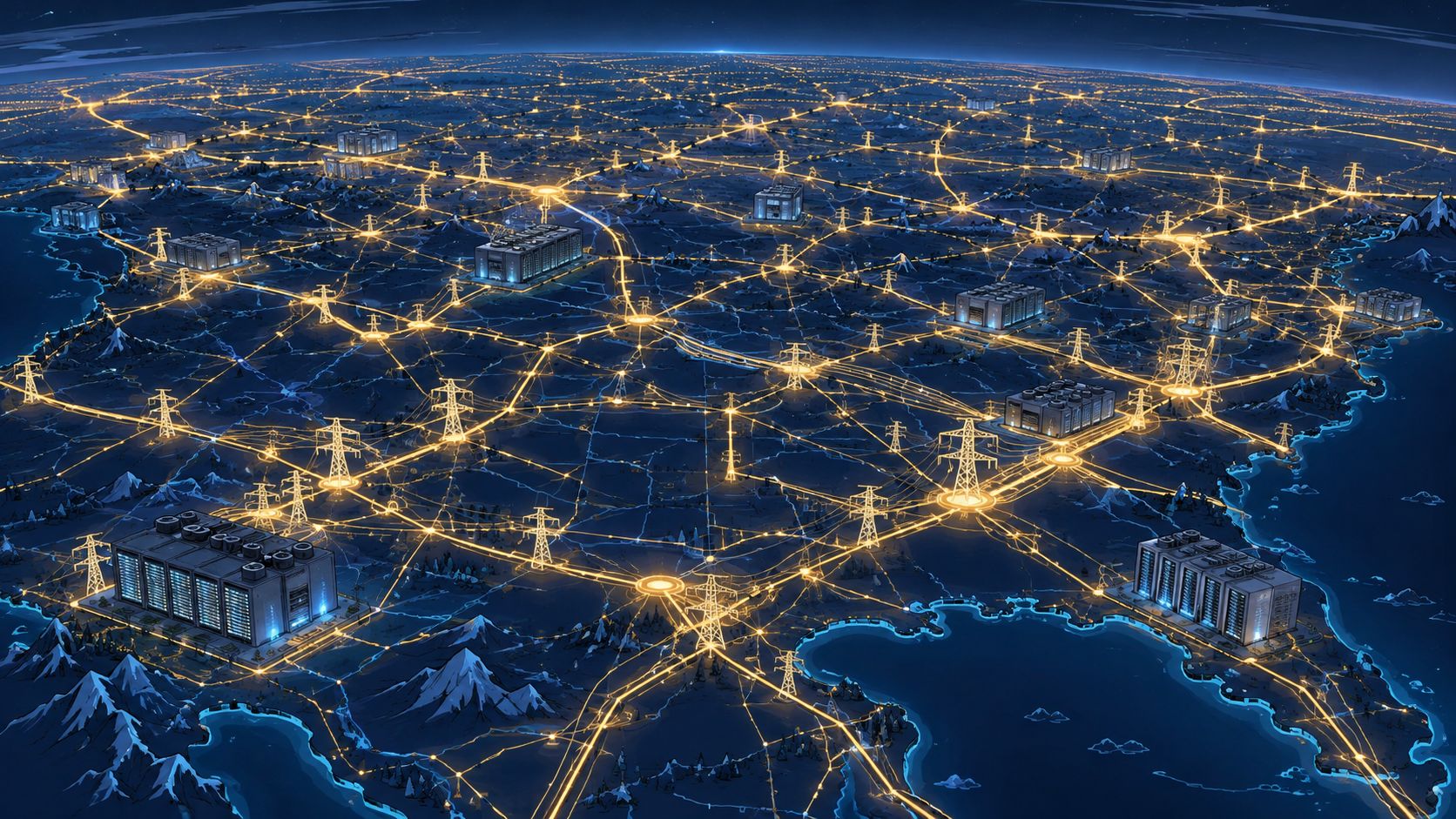
At a smaller facility, the utility connection may supply normal operations while on-site generators cover outages. At a utility-scale campus, the facility becomes a major grid participant. Its demand can influence substation planning, transmission studies, protection coordination, voltage stability, and the utility's ability to serve nearby customers.
The planning rule is straightforward:
Power generation decisions should begin with the site's load profile and grid position, not with a preferred generator technology.
The load profile includes more than the IT nameplate. Cooling equipment, pumps, air handling, lighting, controls, battery charging, and electrical losses all add to the generation requirement. Operating flexibility matters too. A continuously powered facility has different priorities from one that can reduce selected workloads during grid stress.
Redundancy also changes with scale. N+1 means the system has one more capacity unit than the load requires, like keeping one spare pump ready while the others operate. At larger campuses, that spare capacity must be evaluated alongside grid availability, generator start time, battery ride-through, maintenance outages, fuel delivery, and emissions limits.
Local due diligence therefore comes before technology selection. Facility managers need to assess transmission capacity, fuel infrastructure, permitting conditions, water constraints, and emergency access. Interconnection delays may increase reliance on temporary or on-site generation, while fuel logistics and emissions targets can determine whether that generation is practical to operate. Global demand creates common pressure, but local infrastructure dictates the generation mix and redundancy design that can be built.
Grid Interconnection and High Voltage Distribution
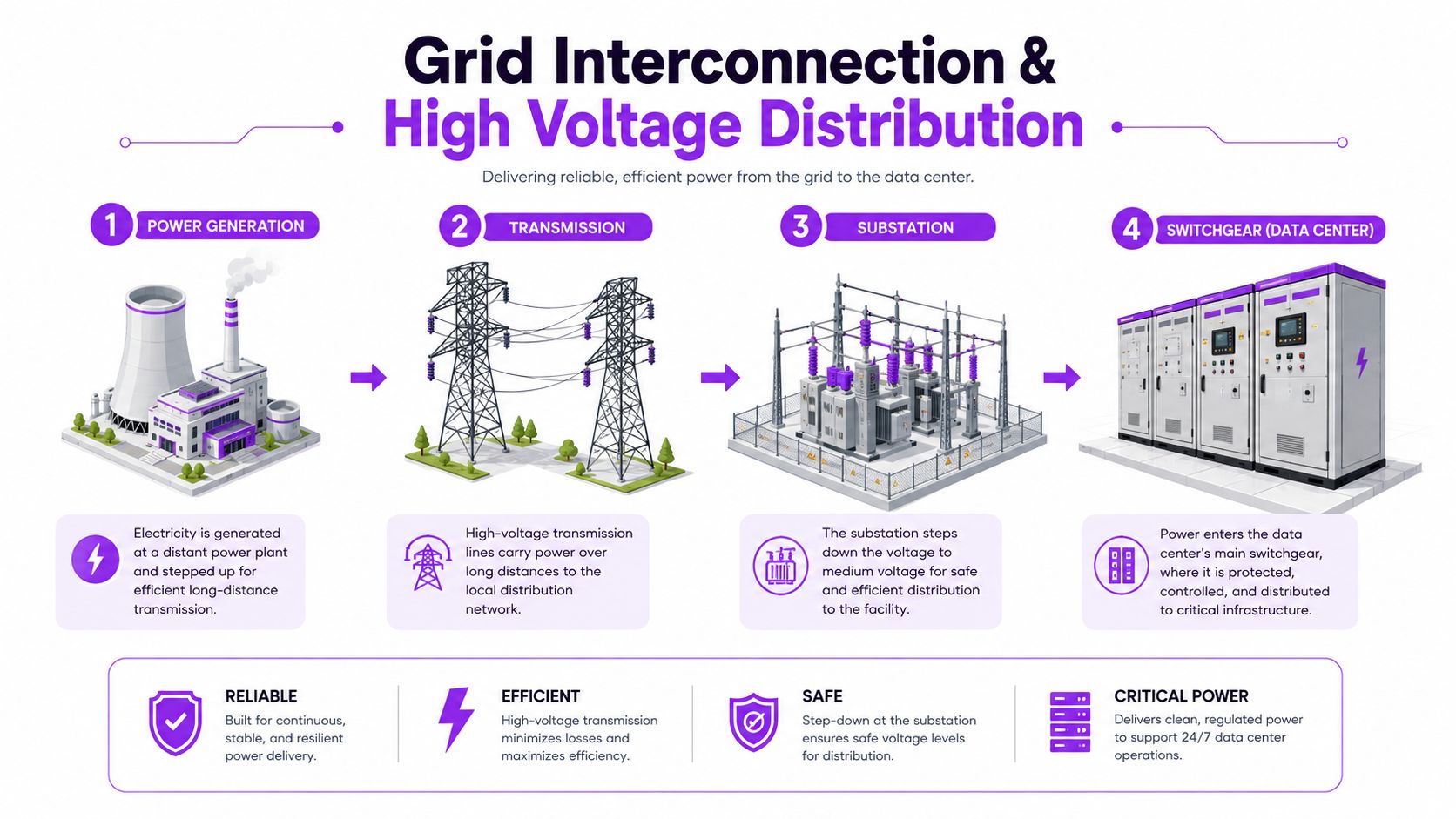
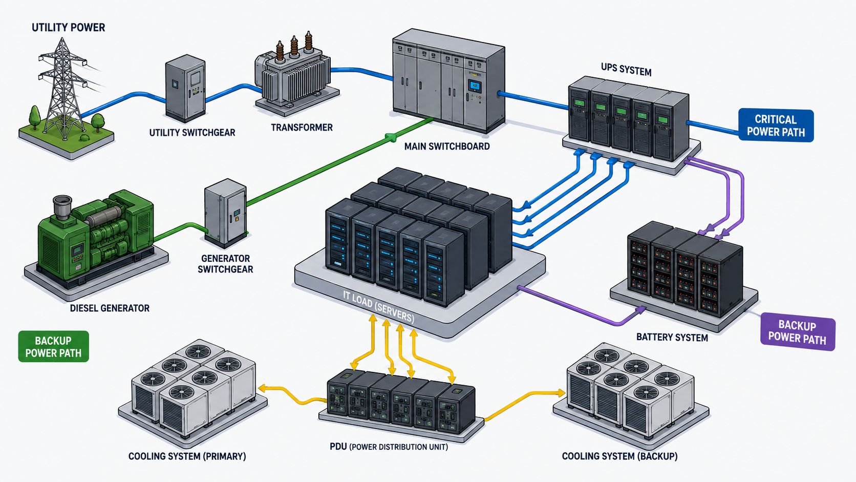
A data center usually connects to the power system through a high-voltage interconnection, rather than an ordinary neighborhood circuit. The grid interconnection overview describes the usual hierarchy: transmission lines deliver power to a dedicated substation, transformers reduce the voltage, and campus distribution equipment carries electricity toward each building.
The route has four stages:
- Transmission arrival: High-voltage lines bring electricity from the wider grid to the project area.
- Dedicated substation: Transformers reduce incoming voltage for campus distribution.
- Medium-voltage network: Feeders distribute power among buildings and electrical rooms.
- Main switchgear: Switchgear controls, protects, and routes power to transformers, UPS equipment, and facility loads.
Why voltage level affects schedule
Large hyperscale sites may receive service at 115 kV or 230 kV, then step it down to 12 kV to 35 kV for distribution across the campus. Higher voltage moves the same power with lower current, reducing conductor requirements and electrical losses along the connection.
The schedule risk begins outside the building. Projects above 100 MW typically require new transmission construction, dedicated substations, and extensive coordination with the grid operator, as described in the interconnection analysis. A finished data hall cannot reach its planned capacity if the transformer bank, protection system, or transmission connection remains incomplete.
The interconnection queue is a design input
Facility managers should treat queue timing and substation availability as design assumptions, not administrative details. If utility service is delayed, on-site generation may provide temporary or permanent supply, but it must still coordinate with protection studies, synchronization, fault levels, operating procedures, and the eventual utility connection. Those constraints connect interconnection planning directly to fuel logistics, emissions targets, and the generation mix.
The early questions are practical:
- What voltage will serve the site? Confirm the transmission connection and campus distribution arrangement.
- Who owns the substation? Ownership affects design responsibility, maintenance, protection coordination, and schedule control.
- What happens during transition? Define how loads move among utility supply, on-site generation, and UPS-backed systems.
- Which equipment has the longest lead time? Transformers, breakers, relays, and transmission work can set the project's critical path.
A substation is the facility's electrical gateway. If that gateway arrives late, generation equipment alone cannot restore the intended operating capacity.
On-Site Generation Technology Options
On-site generation is a portfolio decision, not an equipment shopping list. Each technology should match a defined operating role, while the site's interconnection schedule, fuel delivery options, and emissions requirements determine how much firm capacity the facility needs.
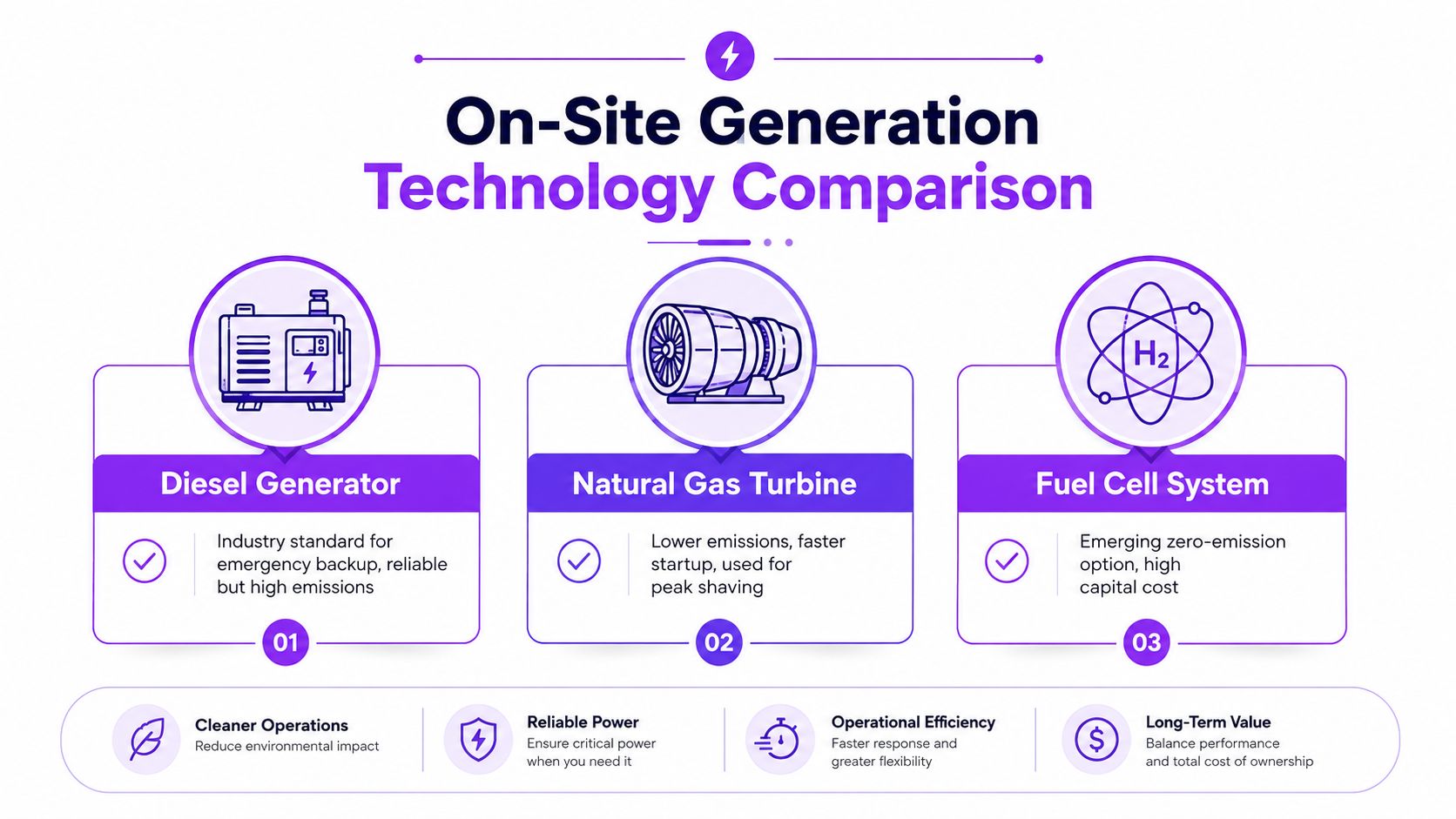
Diesel generators remain common for emergency backup because they start quickly, operate independently of the grid, and keep fuel on site. Their drawbacks become more significant across a large campus. Emissions accumulate through testing, emergency operation, and maintenance runs, while fuel quality, tank capacity, and delivery access require continuous management.
Natural gas engines and turbines can support standby service, peak shaving, or primary generation where the pipeline network can provide adequate supply. Their fuel arrives through infrastructure outside the facility, so pipeline pressure, gas availability, compressor stations, and utility operating conditions become part of the power plan. A gas generator may have available nameplate capacity while its fuel supply remains exposed to curtailment.
Match each technology to its operating role
| Technology | Operational strength | Main planning concern |
|---|---|---|
| Diesel generator | Emergency power with stored fuel and established maintenance practices | Carbon emissions, fuel quality, storage, and delivery |
| Natural gas generation | Potentially continuous operation, standby support, or peak shaving | Pipeline dependence and curtailment exposure |
| Combined heat and power | Uses waste heat for heating or cooling, improving total system utilization | Requires a dependable thermal load and more integrated plant design |
| Fuel cell system | Electrochemical power production without conventional combustion at the point of generation | Higher capital cost and fuel infrastructure requirements |
| Solar and wind with batteries | Reduces dependence on conventional generation during suitable operating periods | Intermittency, land availability, storage duration, and controls |
Combined heat and power can improve overall plant use when the campus has a steady heating or cooling requirement. The electrical and thermal systems must be sized together. If the recovered heat has no reliable use, the expected benefit declines even when the generator performs well electrically.
Fuel cells provide quiet, modular generation without combustion at the point of power production. Their evaluation still requires a site-specific review of capital cost, fuel source, maintenance arrangements, and their relationship with backup systems. Local emissions may be lower, but the full fuel pathway and operating duty remain relevant to environmental planning.
Solar and wind paired with batteries can reduce grid purchases and provide short-duration ride-through. They do not automatically replace firm generation. The storage duration, weather conditions, load profile, control sequence, and recovery plan must all support the facility's worst operating conditions.
Teams researching location and power context can use examining how solar-plus-storage powers a Nevada data center as a site example. The final mix should follow operating duty, interconnection constraints, fuel logistics, permitting requirements, and emissions targets. Technology labels alone do not establish resilience.
Sizing and Redundancy Architecture
Capacity planning answers how much power a facility needs. Availability planning asks what happens when a generator fails, a switchboard is serviced, or an entire supply path becomes unavailable. Those decisions also reflect grid constraints, fuel access, and emissions targets. A long interconnection queue may increase dependence on on-site generation, while emissions limits can restrict which generators run continuously.
Data centers commonly use N+1 or 2N designs. In an N+1 arrangement, “N” is the number of generator modules required to carry the calculated load. The additional unit allows the remaining generators to support that load if one fails or enters maintenance, provided the distribution system and operating procedures preserve the same capability.
A useful comparison is a work crew with one spare member. The crew can continue when one person is absent, but the spare does not duplicate every tool, room, or workflow. A generator may be available while a shared switchboard, fuel system, control circuit, or cooling path remains a single point of failure.
Why 2N costs more than nameplate capacity
A 2N architecture duplicates the complete power path. Separate generator groups, switchgear, controls, and distribution routes create two independent systems. The critical load can then remain supplied if one entire path is unavailable, assuming the systems are physically and electrically separated.
| Architecture | What it protects against | Typical design question |
|---|---|---|
| N+1 | Failure or maintenance of one generator module | Can the remaining train carry the required load? |
| 2N | Loss of an entire power train | Are the two trains genuinely independent? |
The UPS system closes the gap between utility loss and generator start without interrupting sensitive equipment. Batteries provide continuous power during that interval, while power electronics condition voltage and frequency. The UPS supports the transition, but it does not replace firm generation. Its performance also depends on battery capacity, control settings, and the transfer sequence.
Power quality belongs in the redundancy plan
Redundancy includes electrical behavior, not only mechanical availability. Nonlinear loads from UPS rectifiers, variable-speed drives, and power conversion equipment can produce harmonic distortion. It resembles ripples added to an otherwise smooth waveform. Excessive distortion can increase heating, interfere with protection, and shorten equipment life.
Facility teams should confirm generator compatibility with UPS systems, verify neutral and grounding arrangements, test transfer sequences, and review harmonic performance under representative load. They should also test the controls and switchgear as a complete operating chain. A spare generator does not provide resilience if the controls cannot synchronize it or the switchgear cannot transfer the load safely. The final architecture must therefore match the facility's load, grid connection, fuel plan, and environmental operating limits.
Fuel Storage and Supply Chain Management
A generator's runtime depends on the full fuel chain, not only tank capacity. Diesel systems require storage, filtration, testing, polishing, replenishment, spill controls, and delivery routes that remain usable during the emergencies that may interrupt grid service.
Stored diesel can accumulate water, sediment, or microbial contamination. Sampling and fuel polishing protect injectors and engines, while inventory monitoring warns operators before reserves become operationally critical. Rotation also matters. Fresh fuel should not be added to a tank whose condition is unknown.
Diesel and gas create different risks
Diesel keeps physical fuel inventory on site, giving operators more direct control over emergency supply. That control brings storage, inspection, fire safety, environmental, and transport duties. Flooding, storms, accidents, or regional demand can block roads, so a delivery contract does not guarantee access.
Natural gas moves the dependency from trucks and tanks to pipelines and pressure management. The design review should examine single-feed exposure, dual-supply options, pressure regulation, curtailment provisions, and the effect of a wider gas-network disruption. The choice between fuels therefore affects both redundancy and the facility's emissions strategy.
Practical rule: A fuel plan should be tested as an outage plan, not filed as a procurement document.
Connect engineering decisions with logistics:
- Map the supply path: Identify suppliers, routes, access restrictions, and alternate delivery arrangements.
- Monitor the inventory: Use automated measurement and alarms tied to operating thresholds.
- Test the fuel system: Include pumps, valves, filtration, controls, and generator loading in exercises.
- Coordinate contracts: Define delivery priorities, emergency contacts, quality requirements, and escalation procedures.
A site can have adequate nameplate generation and still lack usable resilience if fuel cannot reach the equipment or cannot meet engine requirements. Location matters because access, energy infrastructure, and development conditions shape the practical generation mix. The Crusoe Load 2 facility in Armstrong County, Texas illustrates why those conditions belong in power planning. Review the fuel route with the same discipline used for the grid interconnection and redundancy design.
Emissions Impact and Environmental Trade-offs
A diesel generator's environmental impact depends on more than its nameplate rating. Runtime, electrical output, loading, and the number of operating units determine how much fuel becomes Scope 1 emissions. Modern backup diesel generators emit about 0.79 kgCO2 per kWh, based on the International Center for Emerging Technologies emissions analysis.pdf). The factor applies to electricity produced through combustion.
A 3 MW diesel unit operating for a 500-hour annual test and backup duty cycle would release roughly 1,000 tCO2 per year, according to the ICEF calculation. The example turns a routine maintenance obligation into a visible carbon-accounting item. Testing remains necessary for readiness, while test loading, operating method, and fleet size affect the total.
Scaling the emissions lever
For a 100 MW campus, using backup diesel during grid emergencies implies roughly 39.5 ktCO2 annually, under the assumptions in the ICEF analysis. This scenario is not a forecast for every campus. It shows how a generation mix designed around long grid interruptions can create a large Scope 1 burden.
The interconnection queue and emissions target therefore influence the same design decision. A delayed or constrained grid connection may push a facility toward more on-site generation, while a strict emissions target may favor sources that reduce combustion runtime.
- Standby-only diesel: Provides emergency generation, but testing and outages produce direct emissions.
- Natural gas generation: May lower emissions intensity compared with diesel, while adding pipeline dependence and permitting requirements.
- Fuel cells: Avoid conventional combustion at the generation point, but require review of fuel sourcing, cost, and backup arrangements.
- Renewables and batteries: Can reduce generator runtime when their capacity, controls, and stored energy match reliability requirements.
- Grid supply: Can reduce on-site combustion, although its environmental profile depends on the electricity mix and the project's contractual and regulatory framework.
Emissions and resilience can conflict
Reducing generator tests may improve the emissions record while leaving the equipment less prepared for an outage. Running generators continuously can provide greater operating control, but it increases fuel use, maintenance exposure, and local environmental impact. Facility managers need both results in the same decision model.
Track generator hours, generated kilowatt-hours, fuel consumption, testing practices, load-transfer performance, and the emissions factor used for reporting. Review those records against the reliability service the equipment must provide. A lower-carbon source is useful only when it can support the required load during the conditions that shaped the site's interconnection and redundancy plan.
Integration Strategies for Mixed Generation Systems
A practical approach to data center power generation combines the utility connection, on-site engines or turbines, batteries, renewable sources, UPS systems, and controls in one operating architecture. The goal is not to run every source at once. Each source needs a defined role, while the power management system selects the safest combination as grid conditions, load, fuel availability, and emissions requirements change.
During normal operation, the facility may draw mainly from the grid while renewable generation offsets part of the demand. Batteries can handle short transitions, support power quality, or shift selected consumption. Generators remain ready for defined events, such as a utility outage, an approved test, or a period when the interconnection cannot supply the required load.
The microgrid as an operating system
A coordinated microgrid controller tracks source availability, load priority, breaker status, battery state, generator condition, and grid quality. It works like an operating system for electrical assets, applying predefined rules rather than relying on manual switching during a disturbance.
- Detect the event: Confirm that the utility disturbance is real and determine whether the site should remain connected.
- Support the critical bus: UPS equipment and batteries stabilize the most sensitive loads.
- Start firm generation: Generators or other on-site sources ramp toward the required operating state.
- Transfer and balance: Switchgear establishes the intended source arrangement while controls manage frequency, voltage, and loading.
- Protect priority loads: Noncritical systems can be curtailed if available generation cannot cover total facility demand.
- Restore deliberately: After utility stability returns, the system resynchronizes and transfers back under controlled conditions.
Demand response adds another control layer. A facility may reduce discretionary consumption during grid stress when its operating agreement and workload controls allow it. This can provide a grid service, but only after the site demonstrates that curtailment will not affect critical operations.
Site selection and generation are one decision
A power plant cannot be evaluated separately from the land, transmission route, fuel network, permitting environment, water requirements, and nearby development pipeline. A facility directory such as Data Centers List provides searchable information on locations, operating status, planned and under-construction projects, operators, and disclosed or labeled estimated IT power capacity. That context supports early market comparisons before detailed electrical studies begin.
The Lancium clean campus in Hall County, Texas illustrates why facility context belongs in the power decision. Location, energy availability, and operating objectives influence the generation mix before equipment specifications are finalized.
Design principle: The strongest generation portfolio remains operable when the grid is constrained, fuel deliveries are delayed, emissions limits tighten, or one electrical train is unavailable.
Facility managers should map the full chain, from the interconnection queue and substation scope to generator duty, fuel logistics, UPS transitions, emissions accounting, and control sequences. Use facility location, power-capacity information, operator details, and project status to build a grounded market shortlist before committing to a generation architecture or site expansion.