Data Center Rack Layout: Efficient Configuration Guide
Learn data center rack layout best practices for hot/cold aisles, RU allocation, and cabling. Actionable guidance for operators.
11 min read
A data center rack layout should start with IT load per rack, not with aisle drawings. In today's builds, 4 kW to 6 kW racks are still the most common, but 7 kW to 9 kW racks are now more common than they were in 2023, and some sites are already seeing 100 kW or more at peak rack density, which changes the layout problem completely.
Table of Contents
- Why Rack Density Determines Your Layout
- Planning Space and Airflow Around Rack Density
- Power Distribution and Cable Routing Essentials
- Physical Rack Placement Conventions
- Handling Mixed-Density and High-Density Rows
- Putting It All Together and Answering Common Questions
Why Rack Density Determines Your Layout
The most common layout mistake is drawing the room first and letting equipment fit wherever it can. That works only until the first hot spot appears, the first cable bundle blocks airflow, or a planned row cannot support the load profile it was given. The right sequence is the opposite, classify the intended IT load per rack first, then let density drive aisle arrangement, cooling choice, power paths, and cable routing.
The density spread in current operations makes that sequencing essential. The Uptime Institute's 2024 Global Data Center Survey reports that 4 kW to 6 kW racks remain the most common, while 7 kW to 9 kW racks have become more common than in 2023. The same survey says the average typical rack density across respondents is 8 kW, or 7.1 kW when 11 high-density outlier sites above 50 kW are removed, and some facilities now report peak rack densities of 100 kW or more. Those numbers are not a curiosity, they are the reason a generic floor plan no longer behaves predictably under live load. Uptime Institute 2024 Global Data Center Survey
What density changes first
Higher rack density changes the room before it changes the server. A row that is comfortable at a few kilowatts can become unstable once heat exhaust, service access, and cable bulk all increase together. That is why server sprawl planning is really a density management problem, not just a cabinet-count problem.
Practical rule: if the load per rack is still unknown, the layout is unfinished.
A useful way to think about it is by failure mode. Low-density rows usually fail through poor organization. Higher-density rows fail through heat recirculation, insufficient power segregation, and maintenance access that was never designed into the footprint. The layout therefore has to be matched to the densest credible rack in the hall, not the average one, because the worst-case rack dictates the weakest point in the row.
Planning Space and Airflow Around Rack Density
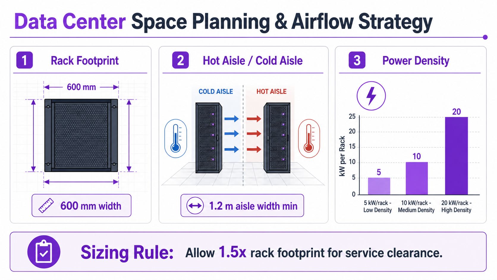
Once density is defined, space planning stops being guesswork and becomes a floor-load problem, a clearance problem, and a thermal problem at the same time. A published sizing guide estimates that a standard IT rack typically requires 37.7 to 53.8 sq ft per rack, with about 65% of the area for white space, 20% for grey space, and 15% for aisles and access. The same guide shows how sharply that footprint expands when power and cooling intensity rise, with high-density air-cooled racks needing 53.8 to 75.3 sq ft per rack, and very high-density liquid-cooled racks needing 64.6 to 96.9 sq ft per rack. Profile IT sizing guide
Space planning should follow the load class
A common planning error is treating every rack as if it deserves the same footprint. Standard enterprise gear can often fit a tighter allocation, but higher-density racks need more room for service access, thermal separation, and the practical mess that comes with dense cabling and cooling hardware. If the floor plan does not leave that room, the racks still go in, but operations get awkward fast.
| Density Category | Sq Ft per Rack | Typical Use Case |
|---|---|---|
| Standard IT Rack | 37.7 to 53.8 | General enterprise deployments |
| High-Density Air-Cooled Rack | 53.8 to 75.3 | Higher-power compute or storage |
| Very High-Density Liquid-Cooled Rack | 64.6 to 96.9 | Dense AI or other high-heat loads |
Airflow still matters, but density changes how much margin you have. In conventional halls, hot-aisle and cold-aisle alignment does the heavy lifting by limiting mixing between supply air and exhaust air. In denser spaces, that same layout needs tighter discipline because the penalties for poor placement show up faster, especially once rows mix different load classes. Academic work cited in the sizing guide found that racks in the middle of a row had the best thermal performance, while servers in higher rack positions performed worst thermally. That finding aligns with what operators see in production, and it is one reason the Syracuse University green data center is a useful reference point when discussing row placement and thermal behavior.
Keep the densest equipment where airflow is most controlled, and do not give premium row positions to gear that can tolerate less favorable conditions.
Power Distribution and Cable Routing Essentials
Power and cabling either support the rack plan or create problems later. In high-availability rooms, redundant rack powering is a requirement, because a clean layout means little if one failed feed drops the rack. Dual independent power inputs, separate upstream paths, and diverse PDUs reduce single points of failure. Structured cabling and environmental sensors help keep maintenance predictable and fault isolation faster. Rack layout and infrastructure guidance
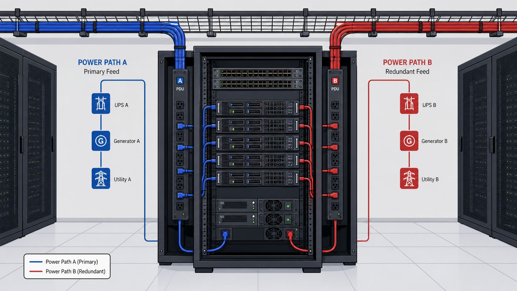
A good example of this approach is a site like Rackmill Perth, where rack-level power design has to support both steady operation and practical service access. That kind of environment shows why dual feeds are more than a diagram exercise. Once you have mixed equipment in the same row, the power plan has to survive swaps, growth, and maintenance without forcing a full-row shutdown.
Dual power paths beat single-path simplicity
Single-ended feeding looks tidy on paper, but it leaves a row brittle. If one upstream path fails, the rack has no graceful fallback. Dual feeds with separate PDUs take more planning and make installation less forgiving, yet they are the right choice wherever uptime matters and maintenance windows are tight. In production, the extra coordination is cheaper than an avoidable outage.
Cable routing deserves the same discipline. Loose or tangled cabling does more than look messy, it blocks airflow and slows troubleshooting when a live rack needs service. Keep power and data paths separate. Route them cleanly so they do not spill into cold or hot aisles, and leave enough slack for service without creating loops that trap warm air.
Route for maintenance, not just installation
Overhead cable trays are usually the safer option when the room already supports them, because they keep the floor clear and cut trip risk. Underfloor routing can still work in older rooms, but only if the airflow strategy and floor access were designed for it from the start. The wrong move is to let routing follow whatever is easiest during install, because the correction later is almost always more expensive than the shortcut.
Serviceability is the true test. If a technician has to reach deep into the row, pull back a bundle, and expose a power path just to replace one component, the cabling plan is too dense. Layouts that hold up in operations leave space for hands, tools, and clear tracing, not just the equipment footprint.
Mixed-density rows make this even more unforgiving. High-density AI cabinets, standard enterprise racks, and liquid-cooled systems do not all tolerate the same cable path or service clearance, so the routing plan has to reflect the row's actual mix instead of assuming uniformity. The layouts that age well are the ones that preserve access at the rack face, keep service loops controlled, and avoid forcing every change into the same narrow maintenance corridor.
Physical Rack Placement Conventions
A good rack looks boring because the layout rules are doing their job. One institutional guideline recommends reserving the top 6U for network infrastructure, placing the heaviest equipment at the bottom for stability, keeping preferred depth at up to 4 feet, and routing data cabling above the rack in independent suspended trays. It also calls for aligning the rack front with the floor tile edge and using fully adjustable, vendor-neutral rails that comply with EIA-310 19-inch equipment standards. University of Arkansas rack guidelines
Why those conventions hold up
The top-of-rack network placement shortens patch runs and reduces the amount of cable that has to be managed around dense compute gear. Heavy gear at the bottom lowers the tipping risk that shows up when storage or UPS units are installed low in the cabinet. Keeping the rack depth controlled protects aisle clearance, which matters more in a room where service teams already have to work around power feeds, fiber, and airflow boundaries.
The front alignment rule sounds minor until the first row starts drifting out of line. Once that happens, cable reach changes, access angles get awkward, and the row stops feeling like a system. Precision in physical placement makes later maintenance more predictable because each rack behaves like the others.
Layout discipline pays off most during maintenance, when the room is crowded, the clock is running, and nobody wants to discover that a cable can't be reached without moving a neighboring cabinet.
There's a reason these conventions persist across organizations. They reduce cable strain on network ports, preserve clean intake paths in the cold aisle, and keep the heaviest hardware from turning a service visit into a stability problem. The details are practical, not ceremonial.
Handling Mixed-Density and High-Density Rows
Many rack layout guides stop helping at that point. Conventional hot-aisle and cold-aisle discipline still matters, and blanking panels still matter, but those rules were built around a more uniform room. Mixed-density halls break that assumption, especially when standard racks sit next to liquid-cooled AI systems or other high-heat deployments that no longer behave like ordinary enterprise gear. Industry guidance also continues to emphasize keeping cable and power paths clear, which is sound, but it doesn't fully solve the geometry problem created by heterogeneous load profiles. APC guidance on rack layout and airflow discipline
Mixed rows need thermal zoning, not just aisle labels
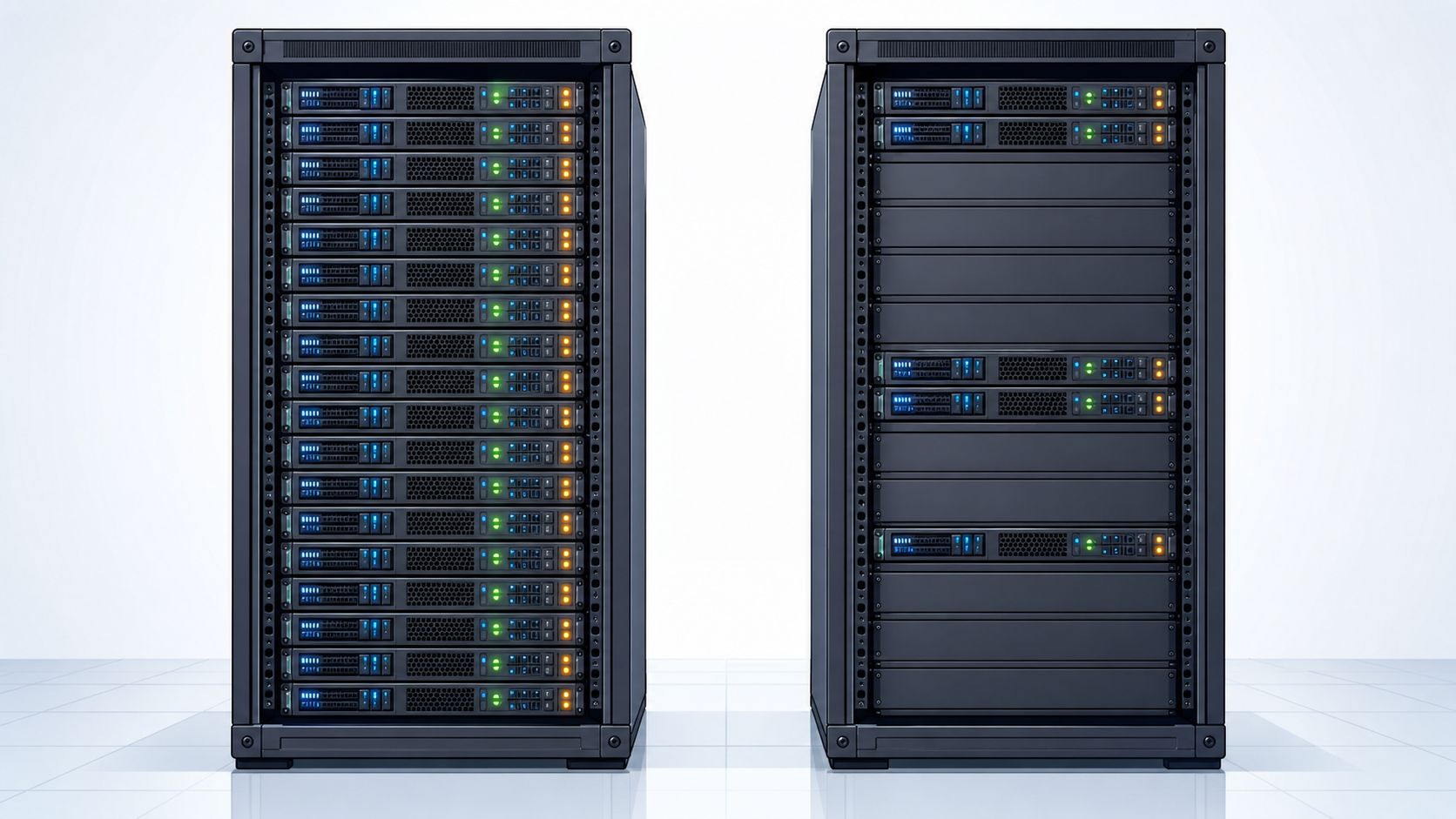
A row with uniform equipment can often be treated as one thermal unit. A mixed row cannot. The hotter rack will pull on its neighbors, and the weaker airflow path will show up as a service issue long before it shows up as a design note. That's why operators need rack-by-rack zoning, tighter placement logic, and a willingness to separate incompatible loads instead of forcing them into the same neat sequence.
High-density AI deployments have made that challenge more visible. Public reporting in 2025 shows many new AI data centers targeting far higher power per rack than legacy enterprise builds, which creates a planning gap for row spacing, service clearances, and rack-specific thermal zoning within the same hall. That doesn't mean every hall needs a full redesign. It does mean that a room designed around one air model can fail when a much hotter rack lands next to a conventional one.
What works when density is uneven
The best answer is usually selective separation. Put the densest or most thermally demanding gear where the room can support it, then avoid mixing it casually with low-density rows that depend on simple aisle behavior. Use blanking and cable segregation aggressively, but don't expect them to solve a mismatch in heat load by themselves.
A second, less obvious move is to protect service access first. Dense racks create more maintenance friction, and if the room has no spare working room around them, every intervention disturbs nearby equipment. Mixed-density layouts need operational breathing room more than symmetrical rows do.
If the hall contains both conventional and high-density racks, the row plan should be built around the worst thermal case in that cluster, not the average one.
Putting It All Together and Answering Common Questions
A solid rack layout sequence stays simple. First classify rack density, then allocate space, then design power and cable paths, then lock in physical placement, and finally decide how to isolate any high-density or liquid-cooled rows that don't fit the standard pattern. That sequence avoids the trap of designing around the cabinet shell while ignoring the heat, power, and service behavior inside it.
Three questions come up repeatedly. Can an existing hall be retrofitted for mixed density? Yes, but only if the densest rows get their own thermal and service logic rather than being dropped into a generic layout. Is hot-aisle containment worth it at lower densities? Sometimes, but the benefit depends on how tightly the room is already controlled and whether the operational team can maintain the containment without creating service friction. What spacing should never be compromised? The answer is the spacing needed for safe maintenance, cable integrity, and stable airflow around the specific load, because once those are lost the rack plan stops being operationally useful.
The right goal isn't perfect symmetry. It's a layout that still works when workloads change, racks heat up, and maintenance teams need access without disrupting neighboring systems. That flexibility should be designed in from the start, because reworking a live hall always costs more than preserving options during the first build.
For operators who need a broader view of facilities, load profiles, and market context, Data Centers List makes it easier to compare sites and understand how real-world capacity is distributed. Use it to sanity-check planning assumptions, see how different facilities are organized, and ground your next data center rack layout discussion in actual market conditions.