Data Center Layout Design: Efficient Floor Plans
Master data center layout design with strategies for zoning, scaling, and airflow. Optimize space, power, and cooling efficiency today.
15 min read
Popular advice treats data center layout design like a drafting exercise, as if racks, aisles, and cooling gear can be dropped into almost any empty shell. That approach fails in real buildings, because a floor plan is really a negotiation between business load, structural constraints, service access, and cooling behavior. The better starting point is requirements analysis, then physical mapping, then equipment placement, then the floor plan lock, exactly in that order.
A layout that looks neat on paper can still fail operationally if it ignores columns, odd wall breaks, or the actual connected load of the IT stack. Modern facilities have moved away from simple room-based placement and toward measurable density and efficiency targets, because the floor plan determines how much IT load fits in the footprint without breaking airflow or expansion space. The result is straightforward, if uncomfortable, the room is never the plan, the workload is.
Table of Contents
- Rethinking the Data Center Layout Design Process
- Mapping Physical Constraints and Room Geometry
- Optimizing Layout Efficiency and Density Targets
- The Impact of Layout on PUE and Cooling Performance
- Adapting Layouts for AI-Driven Density and Liquid Cooling
- Implementing Modular Pod Designs for Scalability
- Validating Your Layout Against Long-Term Goals
Rethinking the Data Center Layout Design Process
Carnegie Mellon's guidance is clear about sequencing, requirements first, floor plan second. It recommends a top-down flow that starts with requirements analysis, then maps physical space constraints, hardware placement, and operational processes before the floor plan is locked in. That order matters because a generic square-foot target can look efficient while hiding the limiter, rack count, utility demand, service clearance, or a cooling path that becomes ugly once the room is full.
Start with load, not square footage
A common mistake is to ask how many square feet a facility has, then back into a design from there. Experienced design practice pushes the opposite, define the IT and business needs first, then translate them into rack units, connected load, and support space. Density varies sharply by equipment mix, so floor area alone tells almost nothing about usable capacity.
That's especially important in retrofit work. The building might have enough gross space, but not enough access for cable routing, maintenance movement, or equipment replacement. A layout that meets a target area can still fail if it can't be operated safely once the racks are live.
Practical rule: if the early conversations revolve around room size instead of workload, the project is already drifting toward the wrong metric.
A disciplined process also protects downstream decisions. Utility sizing, cooling strategy, fire zones, and service aisles all depend on the shape of the actual load, not an abstract shell. The most durable layouts are the ones that reflect how the facility will be used, not how easy the drawing was to draft.
For market scanning and site benchmarking, the facility context matters too, and a global directory such as Data Centers List helps teams compare sites against operational realities rather than brochure language.
Translate business needs into floor logic
The output of requirements analysis should be concrete. A team should know what needs rack space, what needs shared white space, what needs maintenance clearance, and what has to stay isolated for power or cooling reasons. Once those answers exist, the floor plan becomes a response to reality instead of a wish list.
That's the difference between a build that scales and one that immediately feels cramped. A good layout is less about filling a room and more about preserving the ability to change the room later.
Mapping Physical Constraints and Room Geometry
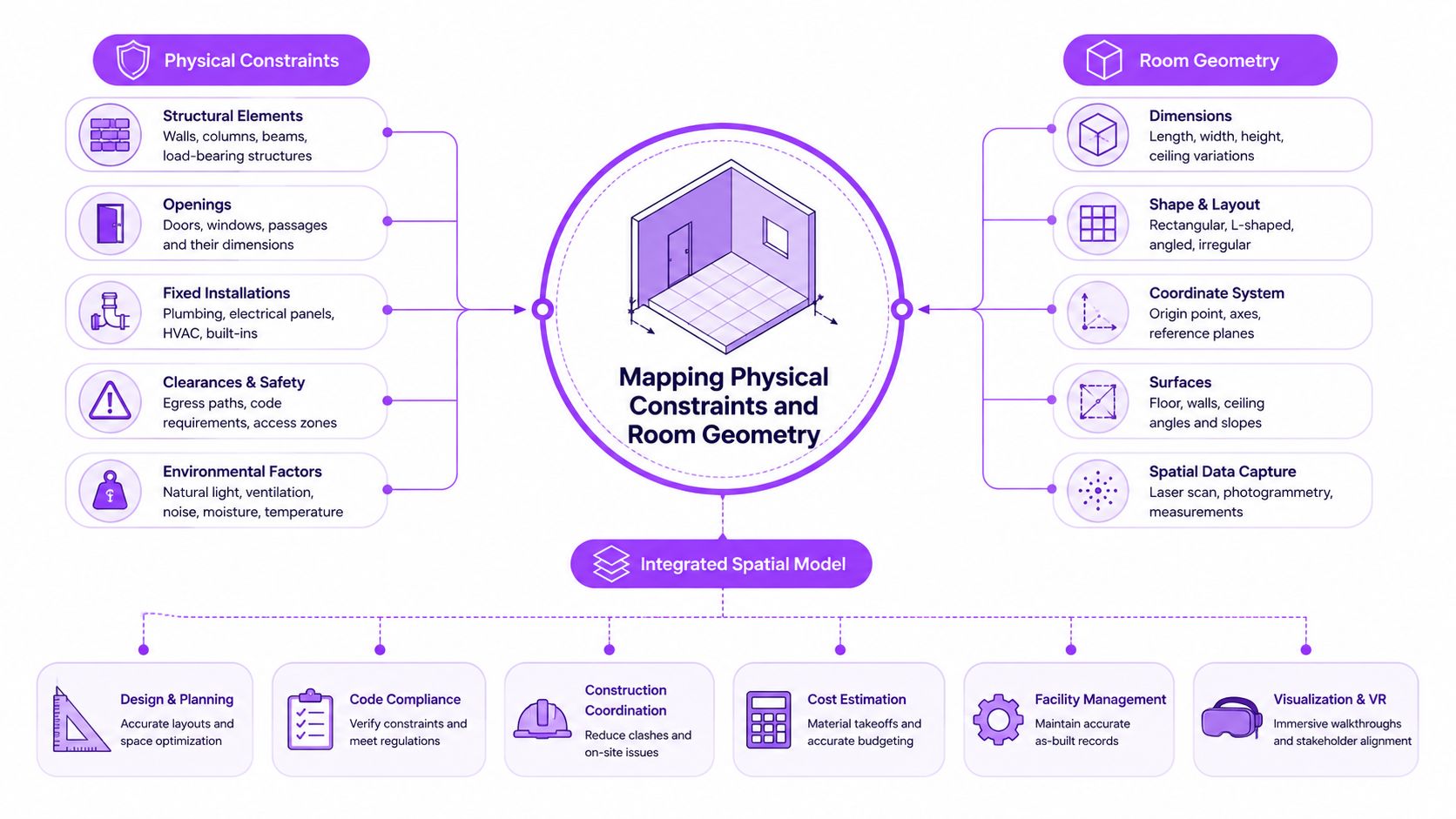
Real buildings punish idealized drawings. Columns appear in the worst possible places, walls aren't always parallel, doors cut into valuable runs, and odd niches create dead zones that never perform like the rest of the floor. A rectangular room is preferred when possible because unusual shapes, angles, and recessed spaces reduce usable power density and make service movement harder, which is why physical geometry has to be mapped before any row is finalized.
Build the constraint map first
The first pass should be a literal inventory of the room. Mark columns, perimeter walls, doors, fixed equipment, floor penetrations, loading paths, and any structure that can't move. That map becomes the boundary of the design, because a rack row that looks clean in plan view can fail the moment a technician tries to move a cabinet past a column or into a narrowed aisle.
Next, align rows to a single axis where possible. That simplifies airflow, makes cable paths more predictable, and preserves service access. It also reduces the chance that an awkward row orientation creates a hidden bottleneck around a corner or at a doorway.
Treat retrofit sites differently from greenfield shells
Brownfield facilities rarely offer clean geometry. In those spaces, the goal is not perfection, it's containment of the damage caused by the building's quirks. Columns should be treated as hard constraints, not decorations to be routed around late in the process. Doors and perimeter walls need early clearance checks, because the service path matters as much as the rack footprint.
One useful habit is to sketch the unusable space as aggressively as the usable space. If a niche can't support a standard row without creating a service hazard, it should be treated as excluded capacity, not “future opportunity.” That discipline prevents false optimism about how much equipment the building can really support.
Hard lesson: a floor plate is only as useful as its worst obstruction.
The same logic applies to access ways. Aisles have to support movement without collisions, and that means the plan needs enough room for equipment removal, not just installation. The layout should be checked from the standpoint of a technician pushing a rack, carrying a component, or navigating a maintenance route under real conditions.
Done properly, geometry mapping turns a messy shell into a workable grid. Done late, it becomes the reason the site is forever constrained.
Optimizing Layout Efficiency and Density Targets
Layout efficiency is measurable, not decorative. The U.S. National Institutes of Health design guide defines layout efficiency as racks per 1,000 square feet, and says the typical range is 20 to 30, with higher values preferred, while also noting that a high-density data center typically houses racks at 14 kW and above, according to the NIH Sustainable Data Center Design Guide. Those figures matter because they tie the floor plan directly to IT load, airflow, service access, and expansion space.
Density changes what counts as efficient
A layout with more racks isn't automatically better. If the extra cabinets choke aisle access or force awkward cooling paths, the room becomes denser but less usable. The target is useful density, which means the floor can carry the load while still allowing maintenance and future growth.
The 14 kW and above threshold is a useful warning line because it signals a different design problem. At that level, simple assumptions about uniform rows and ordinary cooling margins stop working well. The floor plan has to support higher thermal loads without creating hot spots or service dead ends.
Read the room, not just the spreadsheet
A retrofit site with columns or irregular edges may show a respectable square footage number but still underperform on rack density. That happens because the measured floor area includes space that can't really be used for equipment. Layout efficiency gives a better view of the actual result, since it captures how much IT load fits in the supported footprint.
The operational test is serviceability. If a cabinet can't be removed, moved, or maintained without disrupting nearby rows, the design is too tight even if the rack count looks attractive on paper. Aisle clearance is not optional padding, it's part of the capacity model.
| Metric | Typical Range | High-Density Target |
|---|---|---|
| Layout efficiency | 20 to 30 racks per 1,000 square feet | Higher values preferred |
| Rack power level | General facility mix varies | 14 kW and above |
| Operational goal | Preserve service access and expansion space | Maintain access under denser layouts |
That table hides a simple truth, density only matters if the room can still be worked in. Layouts that chase a higher count without protecting aisle clearance often create future outage risk, because every maintenance action becomes a physical event.
The best floor plan doesn't maximize the room, it maximizes the room's usable life.
The Impact of Layout on PUE and Cooling Performance
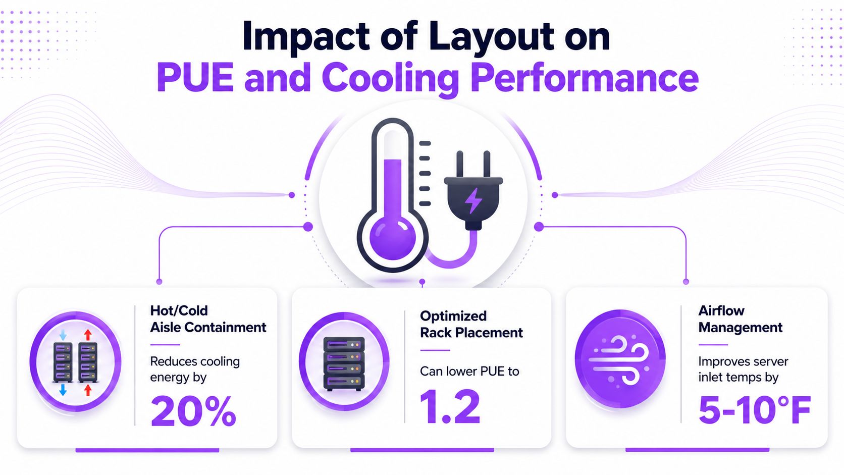
Physical arrangement shapes energy performance in ways that show up at the facility level. A 2026 industry summary citing Uptime Institute data reports that hyperscale facilities achieve PUE values of 1.08 to 1.12, while the global average for colocation facilities is about 1.45 to 1.58, and it defines PUE as total facility power divided by IT equipment power with a theoretical perfect PUE of 1.0, per the industry summary on typical data center layout and infrastructure. That gap is not just about equipment procurement, it reflects how well the layout supports airflow containment, separation of heat zones, and short distribution paths.
Why aisle arrangement matters
Hot and cold aisle planning is not a cosmetic convention. It is a way to keep exhaust from recirculating into intake paths, which protects inlet temperatures and reduces the cooling burden on the room. When racks, power feeds, and cooling paths are arranged cleanly, the facility wastes less effort correcting avoidable mixing.
That is where layout and power efficiency become inseparable. If the room geometry forces long distribution runs or tangled service paths, the infrastructure has to work harder to deliver the same result. The floor plan becomes part of the energy system, not just the container for it.
Containment is a layout decision, not an afterthought
Operators chasing stronger efficiency outcomes usually treat airflow containment as something that has to be designed in, not patched on. Short straight distribution paths help, because they reduce the distance between supply, load, and return. Separation of heat zones matters for the same reason, since a room that blurs those zones loses control over temperature management.
PUE can be useful, but only if the layout team understands what it measures. It's a facility-level ratio, so a good rack plan can still underperform if the rest of the room undermines it. Likewise, a thoughtful floor layout can make a cooling strategy look far better than it would in a cluttered or mixed-use space.
Keep the metric tied to the room
A low PUE outcome does not happen by accident. It usually follows deliberate choices about rack orientation, aisle containment, and how directly air and power reach the load. The layout either helps those systems work together, or it makes them compensate for each other.
That's why the best teams review PUE as a design consequence, not a finish-line number. If the floor plan fights airflow, the energy penalty shows up later and is harder to fix.
Adapting Layouts for AI-Driven Density and Liquid Cooling
AI changes the room faster than most legacy layouts can absorb. Traditional rows assume broadly similar cabinets, similar thermal behavior, and a cooling model built around air movement. High-density AI clusters break that assumption, because the core problem becomes uneven heat, uneven power draw, and the need to position supporting infrastructure much closer to the load.
Uniform rows versus clustered zones
Uniform server rows are comfortable to draft and easy to understand. They fail when a facility has to host a few extreme-density zones alongside ordinary compute, because a one-size aisle strategy wastes space in some areas and starves others of cooling and power. A power-aware layout is better, since it assigns space based on the actual thermal and electrical profile of each cluster.
That's where modular, liquid-cooling-ready zones start making sense. They let the facility treat high-density blocks as special-purpose areas instead of forcing them into a generic floor rhythm. The room becomes more honest about what each part of the load needs.
The Leibniz Supercomputing Centre facility context is useful as a reminder that high-performance environments are already pushing physical planning toward tighter integration of compute, cooling, and utility design.
Seal openings and shorten the path
U.S. Department of Energy material still emphasizes sealing openings, keeping ducts short and straight, and preserving raised-floor clearance in data center design, according to the DOE best practice guide. Those principles matter even more when density rises, because every leak, bend, and obstruction becomes more expensive in thermal terms.
AI infrastructure also creates a placement problem for network and power support. High-speed links have limited reach, so switches, distribution points, and coolant-related components can't be pushed arbitrarily far from the racks they support. The floor plan has to be drawn around those realities, not the other way around.
Design shift: in AI-heavy rooms, the floor is no longer a uniform chessboard, it's a set of thermal and power zones.
That shift rewards layouts that accept unevenness. A room with one dense cluster and one lighter cluster is often more realistic than a room pretending every cabinet behaves the same way.
Implementing Modular Pod Designs for Scalability
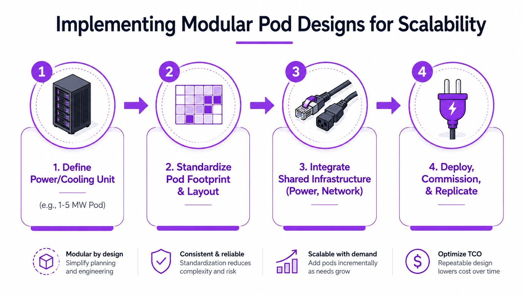
A scalable facility rarely grows smoothly across the whole floor. It grows in chunks. Modular 1 to 5 MW pod design is a practical best-practice because it lets operators add capacity in increments instead of overbuilding upfront, and the pod becomes the unit of expansion rather than the entire building.
Design each pod as a self-contained zone
The first move is to define a pod boundary that can stand on its own for power, cooling, and communications. Once that boundary is clear, the footprint, row pattern, and support services can be standardized inside it. That keeps the expansion method repeatable, which matters when the facility needs to add capacity without rewriting the whole floor.
Shared infrastructure still has to be planned carefully. Power feeds, network trunks, and maintenance paths should be arranged so one pod can come online without dragging another pod into a rework cycle. The goal is independence where it counts and standardization where it helps.
Replication beats reinvention
A pod that can be deployed, commissioned, and then copied is easier to scale than a bespoke block that has to be rethought each time. The best layouts use a clear template, then repeat it as business demand grows. That makes scheduling, procurement, and maintenance more predictable.
For a large campus, that also helps limit exposure to overbuild. Instead of filling the entire shell with capacity that may sit unused, the operator can bring online what's needed and preserve room for the next block. The layout becomes a growth framework, not a one-time allocation.
Keep the pod boundaries honest
A pod should not depend on a future promise to become functional. If it needs a shared utility that hasn't been built, it isn't really modular yet. That's the standard that keeps scaling plans from becoming stranded drawings.
The Hut 8 River Bend AI data center campus is a useful reminder that campus-scale growth works best when each added block has a clear role in the larger capacity plan.
Validating Your Layout Against Long-Term Goals
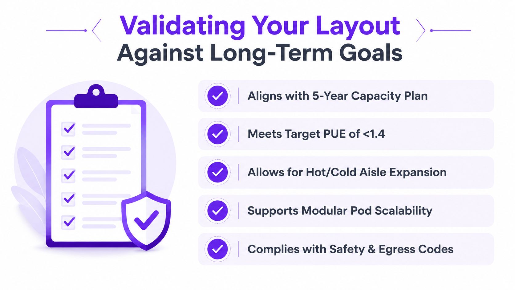
A floor plan is only as strong as its ability to survive growth, density shifts, and maintenance pressure. The final check should test whether the layout supports the five-year capacity plan, preserves hot and cold aisle expansion, fits modular pods, and respects safety and egress requirements. If any of those fail, the design is incomplete.
Check the design against the operating future
The most useful question is simple, can the layout still work when the room is fuller, hotter, and harder to maintain. That question catches weak assumptions early, before the build hardens into expensive reality. It also keeps the team honest about whether the layout is built for today's load or tomorrow's.
A good validation pass should compare the physical plan against the operational plan. If the facility will need stronger density later, the room should already have a path for that shift. If the business expects pod growth, the layout should show where that growth lands without disrupting live operations.
Use a simple pass fail review
A practical review can be reduced to a few questions:
- Capacity alignment: Does the plan match the actual growth forecast, not a generic floor target?
- Efficiency fit: Does the layout support the intended PUE outcome and airflow strategy?
- Geometry realism: Have columns, doors, niches, and wall breaks been fully accounted for?
- Density readiness: Can the room absorb higher-density clusters without forcing a redesign?
- Operational access: Can teams move equipment, service racks, and expand aisles without collisions?
That list works because it forces the design to answer for both structure and operations. A floor plan that passes those checks is much more likely to age well.
Data Centers List gives operators, developers, and site-selection teams a practical way to compare facilities by status, location, and capacity context instead of relying on outdated assumptions. If the next layout decision depends on understanding where existing, planned, and under-construction sites fit into the market, visit Data Centers List and use it to ground the conversation in real facility data.