Data Center Classifications: A Complete Reference Guide
Explore the major data center classifications, from Uptime Tiers to TIA-942, EN 50600, and ownership models. A reference guide for operators and analysts.
20 min read
A data center's reliability label can conceal a major operational difference. The commonly cited model places annual availability at 99.671% for Tier I and 99.995% for Tier IV, but uptime is only one part of a facility's real-world profile. A site with high fault tolerance may still differ materially from another site in power density, cooling architecture, water exposure, grid constraints, ownership model, and development status, as the Uptime tier analysis makes clear.
That distinction matters because modern buyers aren't selecting an abstract “tier.” They're evaluating whether a facility can support a workload, a connectivity strategy, a sustainability requirement, or a long-term investment thesis. A useful assessment therefore combines reliability standards with infrastructure scope, subsystem resilience, commercial model, environmental conditions, and the certainty of available capacity.
Table of Contents
- Why Data Center Classifications Matter in 2026
- Uptime Institute Tier Classification
- ANSI/TIA-942 Rating Levels
- ISO/IEC 22237 and EN 50600 Class System
- Ownership and Scale Classifications
- Colocation Subtypes and Carrier Models
- Power, Cooling, and Environmental Classifications
- Pipeline Status and Market Scarcity Signals
- Cross-Reference Matrix for Quick Lookup
- Quick-Reference Summary and Glossary
Why Data Center Classifications Matter in 2026
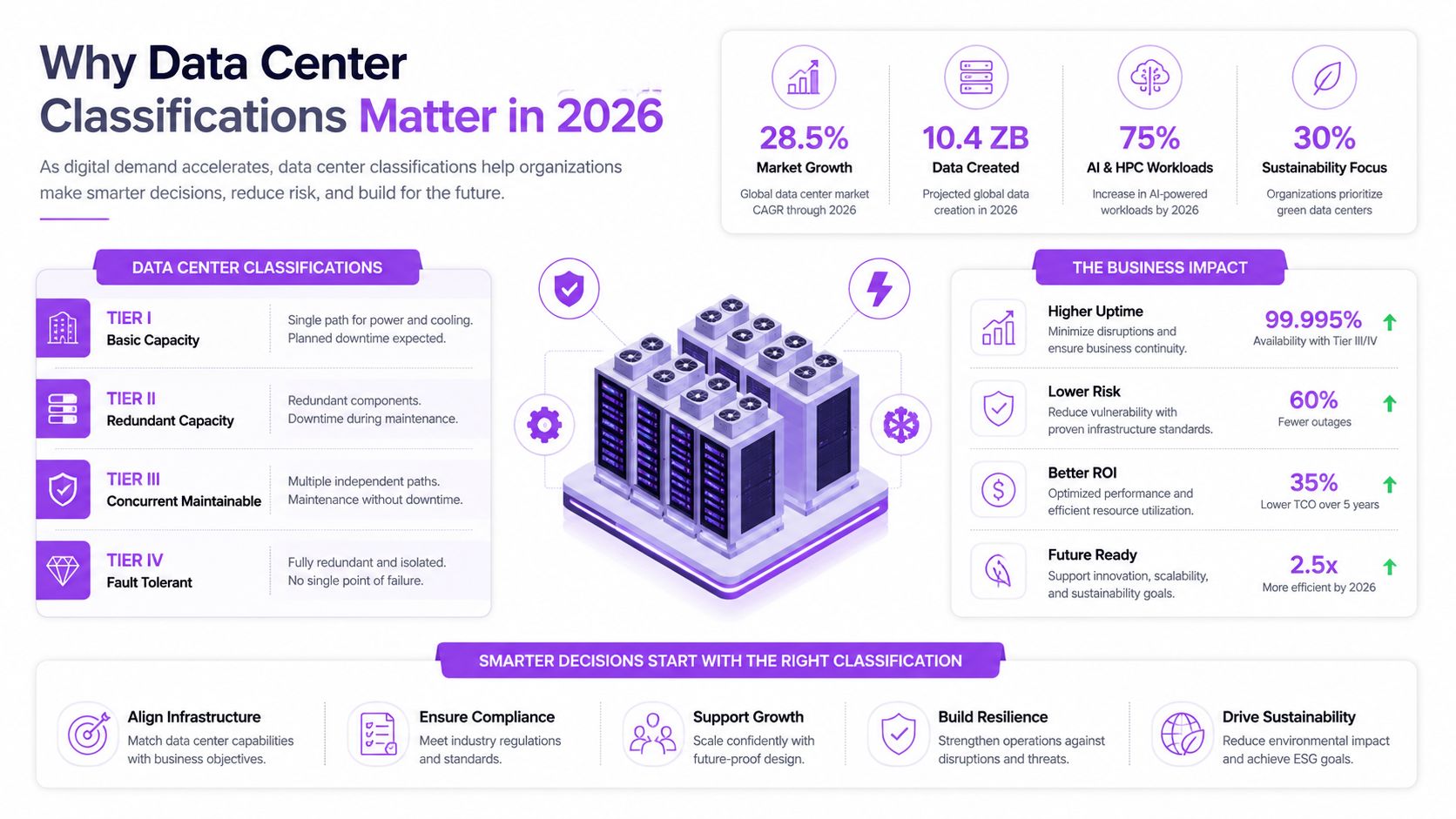
High-density computing is making reliability labels less sufficient for site selection. The classic four-tier framework remains useful, but operators, tenants, investors, regulators, and communities also need to assess water demand, cooling method, rack density, grid stress, ownership, and the certainty of advertised capacity. A facility may be operational, under construction, or only planned, and those conditions have different commercial implications.
Current research materials indicate that a single 100 MW data center may use roughly 2 million liters of water per day on average, while about 725,000 liters per day may be consumed on site, depending on the cooling arrangement and accounting boundary. These figures, documented in research on the limits of tier-only classification, show why facilities with the same uptime label can create different environmental and community impacts.
The modern classification stack
A global benchmark needs several parallel lenses:
- Reliability: Uptime Institute Tier I through Tier IV, focused on availability and fault tolerance.
- Infrastructure breadth: ANSI/TIA-942 Rated-1 through Rated-4, covering electrical, mechanical, architectural, telecommunications, security, and related systems.
- Subsystem resilience: ISO/IEC 22237 and EN 50600, which assign availability and protection classes by domain.
- Commercial fit: Enterprise, colocation, hyperscale, telecom, and edge ownership models.
- Operational impact: Cooling method, rack density, water use, energy efficiency, grid conditions, and carbon profile.
- Market position: Operational capacity, construction status, planned capacity, vacancy, and regional scarcity.
These axes answer different questions. A tier indicates how a facility is designed to respond to failures, while a rating shows how broadly its infrastructure has been assessed. A class-based standard can reveal uneven resilience between power and cooling. Ownership and scale clarify who controls the infrastructure and how tenants procure it.
Market conditions make capacity status part of the analysis. Industry reporting cited in the 2025 data center market overview placed global average vacancy at 6.6% in Q1 2025, down 2.1 percentage points year over year. A resilient facility in a constrained market can therefore hold different strategic value from an equally resilient facility with abundant nearby capacity. Classification is most useful when it connects reliability with capacity, pipeline certainty, cooling, and local resource pressure.
Uptime Institute Tier Classification
The Uptime Institute's four-tier model compresses facility reliability into four levels: redundancy, maintainability, and fault tolerance. It is useful for comparing how critical infrastructure is expected to respond to failures, but it does not describe a site's capacity, cooling method, water exposure, or construction pipeline.
The levels are cumulative in intent, not interchangeable in practice. Tier II adds redundant capacity components, while Tier III focuses on concurrent maintenance. Tier IV adds fault tolerance, meaning a single unplanned failure should not interrupt critical operations.
The four tiers
Tier I provides basic capacity without redundancy. Its commonly cited availability is 99.671%, equivalent to roughly 28.8 hours of downtime per year. Planned maintenance may require a shutdown, and an unexpected equipment failure can interrupt IT operations.
Tier II adds redundant capacity components. Availability is commonly modeled at 99.741%, with about 22 hours of annual downtime. This improves protection during component maintenance or failure, although the distribution path remains a limiting factor.
Tier III introduces concurrent maintainability. Its commonly cited availability is 99.982%, or roughly 1.6 hours of annual downtime. Operators can remove or service planned infrastructure without shutting down the IT environment, provided the work follows the facility's design and operating procedures. A Tier III facility in Vilnius still requires separate checks on capacity, networks, and expansion.
Tier IV combines fault tolerance with fully duplicated critical paths and redundant capacity. Its modeled availability is 99.995%, or approximately 26.3 minutes of annual downtime. The defining test is whether one unplanned failure can cause an interruption. Planned maintenance alone does not establish Tier IV performance.
| Tier | Redundancy Level | Availability | Annual Downtime | Key Capability |
|---|---|---|---|---|
| Tier I | No redundancy | 99.671% | About 28.8 hours | Basic capacity |
| Tier II | Redundant capacity components | 99.741% | About 22 hours | Component maintenance with greater resilience |
| Tier III | Redundant capacity and maintainable distribution | 99.982% | About 1.6 hours | Concurrent maintenance |
| Tier IV | Fully duplicated critical paths | 99.995% | About 26.3 minutes | Fault tolerance |
What the tier label leaves out
Tier classification applies to a defined site scope. A provider should confirm whether the designation covers one building, a complete campus, or a particular phase before applying it to other facilities or services. Certification does not prescribe a building method, cooling technology, sustainability result, water strategy, ownership model, or commercial structure.
For procurement, the tier is a reliability baseline, not a complete asset description. Buyers should pair it with evidence on available power, rack-density limits, network diversity, maintenance procedures, environmental disclosures, and expansion options. Those checks also reveal whether the facility can support the required workload now, rather than only whether its design addresses failure scenarios.
Capacity status matters as much as the label. A certified facility with constrained expansion, an uncertain project pipeline, or high local water stress may fit a different operating strategy from an equally rated site with available power and a clearer development path.
Practical rule: Use the tier to answer, “How does the critical infrastructure handle failure?” Use separate evidence to determine whether the site has the capacity, cooling profile, resource position, and delivery certainty the deployment requires.
ANSI/TIA-942 Rating Levels
ANSI/TIA-942 addresses a broader infrastructure question than the Uptime tier model. Its four ratings are Rated-1 Basic Site Infrastructure, Rated-2 Redundant Capacity Component Site Infrastructure, Rated-3 Concurrently Maintainable Site Infrastructure, and Rated-4 Fault Tolerant Site Infrastructure.
The distinction is important because TIA-942 considers more than the power chain. Its global scope includes site location, architecture, electrical systems, mechanical systems, fire safety, telecommunications, security, and related infrastructure requirements, as described by the TIA-942 certification and ratings framework.
Breadth changes the comparison
Uptime tiers are commonly used as a reliability shorthand. TIA-942 ratings provide a wider infrastructure assessment, with relevant subsystems receiving ratings that reflect their own design and resilience characteristics. Rated-1 represents basic infrastructure and a single-path arrangement. Rated-2 adds redundant capacity components. Rated-3 supports concurrent maintenance through multiple independent distribution paths, while Rated-4 combines redundant capacity with multiple active paths so that a single fault shouldn't cause downtime.
The two frameworks often appear side by side, but they aren't interchangeable certificates. An operator may describe a facility as Tier III and Rated-3 because the concepts align around concurrent maintainability. Even then, procurement teams should confirm the actual certification scope, the audited systems, and whether the assessment applies to the complete site or a defined area.
| TIA-942 Rating | Equivalent Uptime Tier | Subsystems Rated | Concurrently Maintainable | Fault Tolerant |
|---|---|---|---|---|
| Rated-1 | Broadly comparable to Tier I | Broad infrastructure scope | No | No |
| Rated-2 | Broadly comparable to Tier II | Electrical, mechanical, telecommunications, architecture, and related systems | Limited | No |
| Rated-3 | Broadly comparable to Tier III | Multiple infrastructure domains | Yes | No |
| Rated-4 | Broadly comparable to Tier IV | Multiple infrastructure domains | Yes | Yes |
Why certification scope matters
TIA-942 can accommodate facility-specific needs through related addenda and certification approaches for different facility profiles, including edge, hyperscale, and telecommunications-oriented environments. That flexibility makes the standard useful where a single reliability label would flatten meaningful differences between site types.
Certification involves assessment against the Telecommunications Infrastructure Standard for Data Centers. The resulting rating should be read as an audited designation, not merely a marketing phrase. Buyers should request the certificate, scope, rating by relevant area, and any limitations before using it in a global benchmark.
ISO/IEC 22237 and EN 50600 Class System
ISO/IEC 22237 and Europe's EN 50600 take a more granular approach than a single tier or rating badge. They classify data center infrastructure across separate domains, including construction, power distribution, environmental control, and telecommunications cabling. The system also includes protection classes for physical security.
That structure changes the procurement conversation. Instead of asking only whether a facility is “Class 3,” an analyst can ask which subsystems have achieved which class and whether the combination matches the workload's risk profile. A facility could, for example, have stronger power resilience than environmental-control resilience. The value lies in exposing that imbalance rather than hiding it behind one overall label.
Availability is selected by business risk
The framework uses availability classes chosen through business risk analysis. Owners can specify different resilience expectations for separate subsystems, linking investment to the consequences of interruption. This makes the model particularly practical for portfolios operating across countries with different construction practices, grid characteristics, and regulatory expectations.
The class system isn't pass or fail in the simplistic sense. It provides a structured way to document design intent and conformance evidence across the facility's technical domains. The exact assessment should be confirmed through the relevant conformity process and documentation, rather than inferred from a supplier's general description.
| Subsystem | Class 1 | Class 2 | Class 3 | Class 4 |
|---|---|---|---|---|
| Construction | Basic facility provisions | Improved resilience | Higher operational continuity | Highest specified resilience |
| Power distribution | Basic distribution arrangement | Added redundancy | Maintainable distribution | Fault-tolerant distribution |
| Environmental control | Basic environmental support | Redundant capacity elements | Maintainable environmental systems | Fault-tolerant environmental systems |
| Telecommunications | Basic cabling infrastructure | Additional resilience | Maintainable connectivity architecture | Highest specified connectivity resilience |
Protection is a separate axis
Availability classes address continuity of infrastructure operation. Protection classes address physical security. Keeping those dimensions separate helps a buyer avoid a common analytical error, treating uptime resilience as proof of physical protection, or treating strong access controls as proof of power fault tolerance.
A single facility badge can hide subsystem trade-offs. A multi-axis class schedule makes those trade-offs visible to operators, tenants, and investors.
For multi-market portfolios, that transparency is more useful than forced equivalence. A buyer can compare a high-availability power design with a lower environmental-control class, then decide whether the combination fits the workload, budget, and operational model.
Ownership and Scale Classifications
Reliability standards describe infrastructure behavior. Ownership and scale classifications describe who operates the site, who uses it, how capacity is contracted, and how expansion occurs. These labels overlap with tier and rating systems, but they answer a different commercial question.
Enterprise facilities
An enterprise data center is usually controlled by one organization and built around internal workloads. The site may be on premises or located elsewhere, but the owner generally controls the equipment, operating policies, and capacity planning. Procurement emphasizes governance, security, compliance, and lifecycle control rather than open-market leasing.
Colocation facilities
Colocation facilities house multiple tenants under a shared building and infrastructure model. Retail colocation generally serves smaller deployments, while wholesale colocation provides dedicated suites, cages, or larger blocks. The provider operates the facility systems, and the tenant manages its own IT equipment under a service agreement.
Hyperscale campuses
Hyperscale sites are large platform-owned or platform-dedicated environments designed for extensive compute, storage, and network operations. They're typically developed in phases, with campus-level expansion shaped by land, power, fiber, and workload forecasts. Their scale doesn't automatically determine their tier, rating, or environmental performance.
Telecom and edge sites
Telecom facilities sit near network infrastructure and support carrier or communications workloads. Edge facilities place compute closer to users, devices, or industrial systems where latency matters. Edge sites may be small or distributed, but “edge” is primarily a location and workload-purpose classification, not a guaranteed capacity or reliability level.
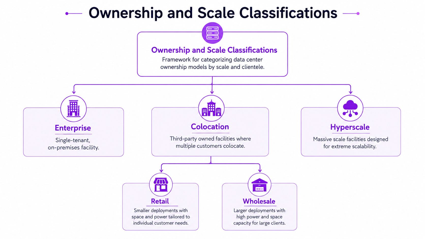
| Model | Control | Tenant Structure | Expansion Pattern | Primary Evaluation |
|---|---|---|---|---|
| Enterprise | Single organization | Single user or affiliated users | Planned around internal demand | Control and workload fit |
| Colocation | Specialist operator | Multiple independent tenants | Contracted blocks or incremental space | Service terms and connectivity |
| Hyperscale | Platform owner or dedicated operator | Primarily internal platform workloads | Large phased campus development | Power, land, fiber, and scale |
| Telecom | Carrier or communications operator | Network-adjacent workloads | Distributed network footprint | Connectivity and latency |
| Edge | Varied ownership | Localized workloads | Distributed, modular, or metro expansion | Proximity and operational simplicity |
The ownership model affects service-level agreements, expansion speed, maintenance responsibility, and exposure to market pricing. A directory such as Data Centers List's operator directory can help analysts connect facility records to ownership portfolios, but ownership should still be verified against current disclosures and facility documentation.
Colocation Subtypes and Carrier Models
“Colocation” describes a shared facility, but it doesn't fully describe the buying experience. Procurement teams should separate retail, wholesale, carrier-neutral, and carrier-captive or single-tenant models because capacity, connectivity, pricing, and contract structures can differ sharply.
Retail colocation
Retail colocation typically sells cabinets, racks, cages, or smaller increments of space. Tenants often need flexible deployment, hands-on services, and access to several network providers. Pricing is commonly structured around cabinet or rack commitments, power allocation, cross-connects, and managed services.
Wholesale colocation
Wholesale arrangements provide dedicated suites, cages, halls, or larger power blocks. Contracts tend to be longer, tenant control is greater, and the customer often takes more responsibility for its internal fit-out. Wholesale sites suit organizations with predictable, substantial requirements that want dedicated space without owning the entire building.
Carrier-neutral facilities
Carrier neutrality is a connectivity attribute, not a size category. A carrier-neutral building hosts multiple network operators and supports cross-connect ecosystems, meet-me rooms, and routing diversity. That can improve choice and negotiating power for tenants that need several carriers, cloud on-ramps, or diverse paths.
Captive and single-tenant models
A carrier-captive or single-tenant facility is optimized around one operator, one platform, or one internal workload family. It may deliver excellent performance for that use case, but tenants generally have fewer independent connectivity options and less flexibility to change providers within the same building.
| Subtype | Typical Scale | Contract Length | Connectivity | Best-Fit Tenant |
|---|---|---|---|---|
| Retail colocation | Smaller cabinet, rack, or cage deployments | Flexible to moderate | Broad carrier choice often available | Growing enterprise or network-intensive tenant |
| Wholesale colocation | Dedicated suites, cages, or large blocks | Longer-term | Selected carrier and cross-connect options | Large predictable deployment |
| Carrier-neutral | Any scale, from room to campus | Varies by space commitment | Multiple carriers and network operators | Tenants prioritizing path diversity |
| Captive or single-tenant | Dedicated operator or internal facility | Structured around one user | Limited to selected network ecosystem | Platform-specific or internal workloads |
The analytical mistake is to treat carrier neutrality as a proxy for scale. A 5 MW retail room in a carrier-neutral building may offer stronger network economics for a connectivity-heavy tenant than a 25 MW wholesale suite in a captive facility, because the two sites solve different problems. Capacity and connectivity should therefore appear as separate columns in every comparison.
Power, Cooling, and Environmental Classifications
Traditional tiers describe continuity under defined failure conditions. They do not show how a facility supplies power, removes heat, or manages environmental constraints. A useful operating profile should therefore add cooling architecture, rack density, water use, energy efficiency, and grid conditions.
This distinction matters for AI and high-performance computing workloads. Higher-density deployments and liquid-cooling adoption became prominent developments in 2025, making a tier-only view too narrow for site selection and impact analysis. Cooling method, available capacity, and local water stress can materially change the suitability of two facilities with the same reliability label.
Cooling and density must be evaluated together
Air-cooled designs generally suit conventional rack densities and can simplify maintenance. Chilled-water and water-cooled systems can support larger thermal loads, while adding mechanical, water-management, and operating requirements. Liquid-to-chip and immersion systems transfer heat closer to the equipment or directly through the cooling medium. They can support higher-density deployments, but require compatible hardware, distribution systems, maintenance procedures, and tenant standards.
Power density should be recorded as a site-specific engineering value, not inferred from the facility's tier. Useful qualitative bands include sub-10 kW per rack, 10 to 30 kW, 30 to 80 kW, and 80 kW or more. Analysts should confirm whether a figure represents average hall allocation, designed maximum, or a committed tenant block.
| Cooling Method | Typical Power Density | Representative PUE Range | Water Use | Best-Fit Deployment |
|---|---|---|---|---|
| Air-cooled | Lower to moderate | Roughly 1.5 to 1.8 | Usually lower direct water dependence | Conventional enterprise and mixed IT |
| Chilled water | Moderate to high | Roughly 1.3 to 1.6 | Depends on heat-rejection design | Larger halls and stable high loads |
| Water-cooled | Moderate to high | Roughly 1.2 to 1.5 | Potentially material | Facilities with suitable water strategy |
| Liquid-to-chip | High-density capable | Roughly 1.1 to 1.4 | Depends on secondary cooling loop | AI and high-performance computing |
| Immersion | High-density capable | Roughly 1.05 to 1.3 | Depends on heat-rejection system | Specialized compute environments |
These PUE values are representative ranges, not certification thresholds. Actual results vary with climate, utilization, redundancy design, and the boundary used for measurement.
Water changes the site-selection equation
A single 100 MW facility may use roughly 2 million liters of water per day on average, with approximately 725,000 liters per day on site. The figures are not universal consumption rules. Climate, cooling design, operating load, and accounting boundaries can produce substantially different results.
The analytical point is direct: uptime classification cannot substitute for water disclosure. Analysts should pair PUE with WUE, grid-carbon intensity, renewable procurement, and regional water stress. A facility carrying the same Tier IV label as another may have a sharply different environmental footprint because its cooling architecture, power sourcing, and local water conditions differ.
Pipeline Status and Market Scarcity Signals
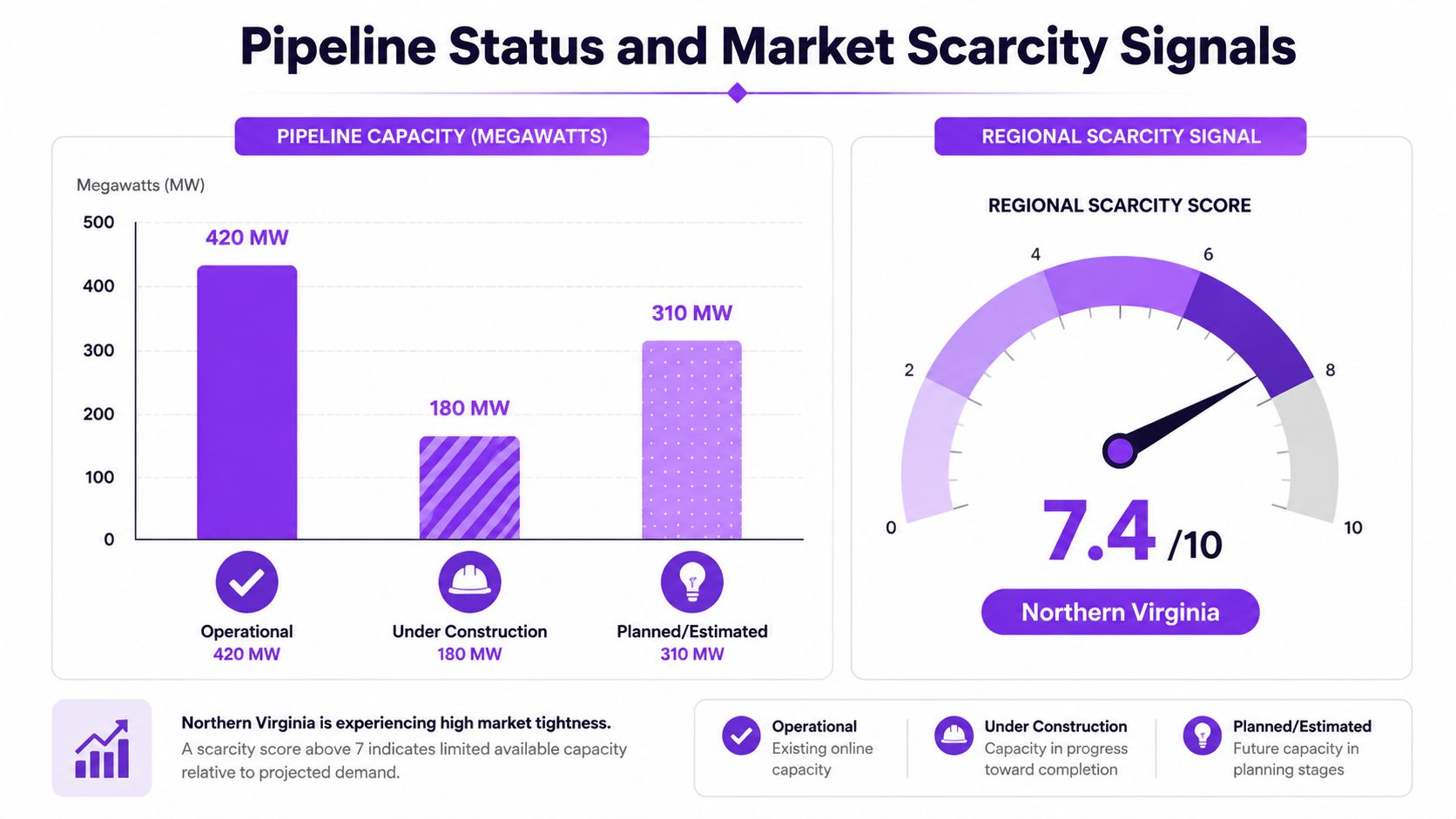
A facility classification should state where the project sits in its development cycle. Operational capacity, capacity under construction, and planned or estimated capacity carry different levels of evidence, even when they appear in the same market pipeline.
Capacity needs a clear definition
Operational MW is capacity serving live infrastructure. IT-load MW is power available to computing equipment, while nameplate MW can describe the rated capacity of a wider electrical system or campus. Analysts must verify the source definition before comparing sites.
Planned capacity also requires qualification. A disclosed project backed by a formal announcement, land position, power agreement, or planning record merits more confidence than an estimate inferred from market signals. Unannounced or speculative capacity should not be counted as immediately available supply.
Scarcity is regional, not just facility-specific
Vacancy, absorption, interconnection queues, land availability, water constraints, and permitting conditions determine whether a facility can satisfy demand. The reported 6.6% global average vacancy rate in Q1 2025, with a 2.1 percentage-point year-over-year decline, shows that available capacity can tighten while a substantial pipeline remains. The figures were reported in market research cited by the 2025 market classification analysis.
A practical scarcity assessment can classify capacity qualitatively:
- Available: Operational space with confirmed power and room for the target deployment.
- Tight: Operational supply exists, but vacancy, connectivity, or power availability restricts choice.
- Constrained: New capacity depends on construction, interconnection, or permitting.
- Speculative: The pipeline is visible, but delivery timing or capacity evidence remains uncertain.
Community stakeholders add a separate test of deliverability. Local moratoriums, water caps, transmission limitations, and interconnection queues can delay a project without changing its reliability designation. Buyers, investors, and planners should therefore record pipeline status beside tier, rating, capacity definition, cooling method, and regional water stress. A reliability label describes resilience. It does not establish how soon capacity arrives, how scarce it is, or whether the surrounding infrastructure can support it.
Cross-Reference Matrix for Quick Lookup
No classification system is sufficient on its own. The matrix below treats each label as one field in a facility profile, not as a substitute for technical diligence. The examples are archetypes, and the final designation must come from site documentation, certification records, operating evidence, and current capacity disclosures.
| Facility Archetype | Uptime Tier | TIA-942 Rating | EN 50600 Availability Class | Ownership Model | Typical Cooling | Pipeline Status |
|---|---|---|---|---|---|---|
| Basic enterprise site | Tier I | Rated-1 | Lower class, subject to assessment | Enterprise | Air-cooled | Operational |
| Redundant enterprise facility | Tier II | Rated-2 | Intermediate class by subsystem | Enterprise | Air or chilled water | Operational |
| Maintainable wholesale colo | Tier III | Rated-3 | Class 3 in critical domains, subject to evidence | Colocation | Chilled water or liquid-ready | Operational or expanding |
| Fault-tolerant hyperscale campus | Tier IV | Rated-4 | High class across selected domains | Hyperscale | High-density liquid or water-assisted design | Phased development |
| Latency-focused regional site | Site-specific | Site-specific | Per-subsystem assessment | Edge or telecom | Air or liquid, workload-dependent | Operational or planned |
How to read the matrix
The first three columns address resilience, but they don't mean exactly the same thing. TIA-942 has a broad infrastructure scope, while EN 50600 and ISO/IEC 22237 can show different classes for power, environmental control, and telecommunications. A Tier III label therefore shouldn't be used to infer identical subsystem performance across facilities.
The final four columns address commercial and operational fit. Ownership indicates who controls the asset. Cooling indicates how the site handles heat. Pipeline status indicates whether capacity can be contracted now or depends on delivery risk.
- Uptime-critical tenants should prioritize maintainability, fault tolerance, certification scope, and maintenance procedures.
- Sustainability-mandated buyers should prioritize cooling, WUE, energy sourcing, grid carbon, and water-stress context.
- Institutional investors should combine certification with operating status, expansion evidence, market vacancy, and infrastructure constraints.
- Community stakeholders should focus on water use, grid demand, construction status, and the credibility of planned capacity.
The useful comparison isn't “Which facility has the highest tier?” It's “Which facility has the right resilience, commercial model, environmental profile, and delivery certainty for the stated risk?”
Quick-Reference Summary and Glossary
The following table condenses the main data center classifications into a working reference. The availability figures shown for Uptime tiers are commonly cited models, not guarantees of actual annual performance, and class or rating equivalence requires confirmation from the applicable certification documentation.
| System | Levels | Core Criterion | Typical Use |
|---|---|---|---|
| Uptime Institute | Tier I to Tier IV | Redundancy, maintainability, fault tolerance, and modeled availability | Reliability benchmarking |
| ANSI/TIA-942 | Rated-1 to Rated-4 | Broad site and infrastructure resilience | Facility design and certification |
| ISO/IEC 22237 and EN 50600 | Four availability classes, plus protection classes | Per-subsystem availability and physical protection | Multi-market design and procurement |
| Ownership model | Enterprise, colocation, hyperscale, telecom, edge | Control, tenant structure, and workload placement | Commercial and operating analysis |
| Operational profile | Cooling, density, water, energy, grid | Physical and environmental fit | Site selection and impact review |
| Pipeline status | Operational, under construction, planned, estimated | Capacity certainty and delivery stage | Investment and market analysis |
The data center terminology reference can support further review of specialist language.
Essential glossary
- Concurrent maintainability: The ability to perform planned maintenance on defined infrastructure without interrupting IT operations.
- Fault tolerance: The ability to continue operating after a defined single failure.
- N: The exact capacity required to support the intended load.
- N+1: N capacity plus one additional component or capacity unit.
- 2N redundancy: Two independent systems, each capable of supporting the required load.
- Carrier-neutral: A facility that provides access to multiple independent network carriers.
- PUE: Power Usage Effectiveness, a ratio comparing total facility energy with IT equipment energy.
- WUE: Water Usage Effectiveness, a measure used to assess water consumption associated with data center operations.
- Hyperscale: A large, highly standardized facility or campus built to support extensive platform workloads.
- Edge node: A localized computing site positioned close to users, devices, or data sources.
- IT-load MW: Electrical capacity intended for computing equipment rather than the complete facility.
- Pipeline status: The stage indicating whether capacity is operational, under construction, planned, or estimated.
For a defensible benchmark, analysts should record the certification scope, subsystem evidence, ownership model, cooling design, water context, capacity definition, and pipeline confidence for every facility. Visit Data Centers List to compare global facilities by location, operator, status, and IT power while separating disclosed capacity from AI-estimated values. Use the directory and map to build a facility shortlist that reflects both technical resilience and the market, infrastructure, and community conditions surrounding each site.